Wednesday, September 8, 2021

Indoor Carbon Dioxide Monitor

 One might ask why someone would want to monitor the levels of carbon dioxide (CO2) in his or her indoor environment. Well, let me tell you about an article that I read in Make Magazine makezine.com.

The article was written by Dale Dougherty and Guido Burger. The essence is that the concentration of CO2 can have a significant effect on the transmissibility of disease. Further, it can have an impact on people's mental acuity. 

Let's look at these in turn. The authors cited an article titled effect of ventilation improvement during a tuberculosis outbreak in underventilated university buildings  ncbi.nlm.nih.gov/pmc/articles/PMC7217216/  While I encourage you to read the article or at least the abstract, the conclusion was that some poorly ventilated rooms at the university were registering CO2 levels above 3,000 parts per million (ppm). When the levels were reduced to under 600 ppm the transmission of tuberculosis from the environment ceased. Of course this doesn't have anything directly to do with CO2 but rather measuring the concentration of CO2 is an easy way to determine how effectively the air is being turned over in an indoor environment. The concentration of CO2 in outdoor air is about 430 ppm.

The second article referenced was Impact of CO2 on decision-making Usha Satish, Mark j. Mendell, et al. 2012. doi.org/10.1289/ehp.1104789  This article found negative impacts on mental acuity that were caused apparently by the higher concentrations of CO2 found in some office environments.

Well, that's enough of that. I encourage you to read the papers but I found this interesting given the current discussions concerning school reopenings with high levels of Covid infections. One of my daughters is a teacher and I thought it would be interesting to build a CO2 monitor that she could place in her classroom. The article in Make Magazine that I mentioned above describes a wonderful assortment of form factors and displays for this type of device. I wanted to build something quickly for my daughter to use and made the device shown on the right. It shows the current CO2 concentration and every 15 seconds adds a bar to the graph. 


Simple is the key word here. There is a microcontroller, a TFT display, a CO2 sensor, and connector to hook them together. Adafruit developed a standard for microcontroller shapes and pinouts such that anything that meets the "feather" standard can be plugged together. I happened to have a Sparkfun esp32 Thing Plus, which adheres to the feather standard. This is a more powerful processor than that required for this project but, as I said I had it just sitting around. From Adafruit I ordered a "TFT FeatherWing 2.4in." display, an "SCD-40 True CO2" sensor and a "STEMMA QT / Qwiic" connector cable.

Once the parts arrived it literally took less than a minute to connect them together. The processor plugs into the back of the screen.


And they look like this when they're put together.


Then it was just a matter of plugging one end of the cable into the processor and the other end into the sensor.


I wrote the software in an afternoon with the help of the example program in the library that supports the sensor and the detailed Adafruit document that supports the display. Then I printed a case on my 3D printer and it was done. In the picture of the case you can see the little cage on the lower edge of the case back on the right in the picture. This is where the sensor sits so it is exposed to the air.


I sent it off to my daughter and will post an update after she has had a chance to try it out.


Wednesday, March 10, 2021

Embroidery Floss Winder


My daughter has a business via which she sells counted-cross-stitch kits, Sew Irreverent. The kits include a pattern and  as many as a dozen different colors of floss. When she puts together these kits she needs to measure the amount of floss in each color to include, as well as wind the floss on a bobbin. As you can imagine this can be very time consuming.

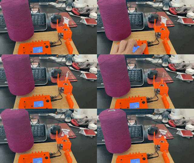
She and I got our heads together and came up with the device shown here to facilitate the process. The heart of it is a small computer that allows her to specify how much floss she wants, and then starts and stops a small motor that winds the desired amount of floss onto a bobbin. Here it is in some more detail.


To the right is a picture of the winder itself. The muscle is a small stepper motor designed to be controlled by a computer. Attached to the shaft of the motor is a cylinder with a slit in it and a peg. These hold the bobbin in place during the winding process. We found that some paper bobbins were a little too flexible to work well by themselves so we made a backer that can be seen in the lower left of the picture. This attaches to the cylinder via the peg and thus provides enough stiffness for the paper bobbins during winding but allows easy separation from the wound bobbin.

In the upper center of the picture is just a simple guide through which the thread is passed before being attached to the bobbin for winding.


Here is the box that contains the tiny computer that controls the winder motor. In the upper right are the wires coming from the motor that connect to the computer.


This picture shows how the device is controlled. The large black button on the right is actually a little joystick. The diamond shape on the screen is the key for the user as to how to specify the length of floss to wind. The default is 3 yards. Pushing the joystick forward increases that number by 1. Pulling the joystick back decreases by 1. Right increases by 10 and left decreases by 10. Pushing downward on the joystick starts the winding process.


We also added a couple of convenience features. The first is a tool for cutting the floss. It is a shroud that holds a standard single edge razor blade. This picture shows the blade being inserted into the shroud.


And in this picture the blade is completely inserted, providing a V-shaped slot exposing a small amount of the blade for easy floss cutting but precluding any hand cutting.

The second convenience feature can be seen in the upper left of this picture. It is a tape measure inlaid into the platform to facilitate any quick measurements.


Finally, here is the whole device as I was packing it up to send it to my daughter. In the back right of the device in the picture you can see the cone shaped pieces that take a standard size spool of embroidery floss.

Well, that's it. If you have any questions please post them in the comments.


Friday, October 11, 2019

MIDI Self-playing Guitar (Part 3)

Last time I told you about my failures in trying to fret guitar strings using a range of techniques. Now I will describe how I actually got it to work.

I used the same method for controlling the vacuum that I described earlier. That is, solenoid valves were controlled by the Arduino Due. When an individual valve was opened it would apply a partial vacuum to a particular pneumatic.

In the picture to the right you can see the plastic pipe that connects the vacuum pump to the solenoid valves, and thence to the pneumatics. Connected to each of the pneumatics is a wire. When the vacuum is applied to a particular pneumatic it pulls on the wire.


Here is the attachment of the wire to the pneumatic. As you may be able to discern this is done through a turnbuckle that I 3D printed. The reason that I went to this trouble is that the length of the wire is critical as you can see in the next picture.


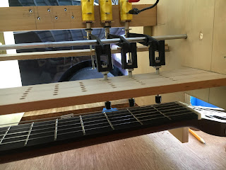
These are the "fingers" that actually press on the strings. The wires from the pneumatics attach to the top of the fingers. Pulling on the wire causes the lower end of the finger to push the string against the fret. As I said, the length of the wire is critical. That is because when the pneumatic is not activated the bottom of the finger must be well clear of string so as not to buzz or damp the string if it is plucked. On the other hand, it must be close enough to the string so that when the pneumatic is activated it presses firmly on the string.

And here is what it looks like overall. The silver wires from the twenty-three pneumatics lead to the compressed space where the corresponding fingers hover about the fret board. Thus, twenty-three fretted strings plus six open strings gives twenty-nine notes or about two and one-half octaves.

And once again here is the link to a quick video that might help to understand how it all goes together in case my explanation is lacking.

Tuesday, September 24, 2019

MIDI Self-playing Guitar (Part 2)


This is a continuation of the description of the design of my MIDI guitar. In the first part I explained how I handled the picking of the strings. Here I will explain the process I went through to handle fretting.

I had used solenoids on the organ and thought that would be a good idea for the guitar as well. Space is tight on the neck of a guitar but my plan was to use levers to transfer the motion from the solenoids into the tight confines of the fret board. Here are  pictures of a prototype.


Another advantage of the levers was that I could trade-off stroke length and force by moving the pivot point of the lever. Unfortunately my solenoids didn't have enough inherent stroke and power to both firmly press the string against the fret as well as withdraw far enough such that they did not interfere with the vibrating string. I tried many different pivot positions but none proved to be dependable enough to satisfy me.


While mulling this problem I happened to think of player pianos. They need a long powerful stroke, especially on the lower keys. And they trigger those key presses via a tiny amount of air drawn through holes in a paper roll.  I didn't know how they worked so once again I matriculated at the University of YouTube.


I found that they used pneumatics designed like little bellows. Here are pictures of the bottom and top of one I made to experiment with. In the first picture the large hole on the right goes through to the inside of the pneumatic. When that hole is connected to a vacuum pump it sucks the top of the device down. However, I needed something to open it back up when the vacuum was removed. I thought about various types of springs, both internal and external. Ultimately, though, I decided to use rare earth magnets. That's what the large blind holes on bottom and top are for. I glued magnets into each of those, with common poles facing each other so they repelled. That seemed to do the trick.

One of the advantage of these pneumatics is that their throw and force can be adjusted by simply changing their size. I made mine about  four inches long and one inch wide, which I think is a typical size for pianos. The purple stuff is a synthetic bellows cloth made specifically for player pianos.
It is pretty air-tight, cuts and glues easily, and is thin and flexible enough to fold well. The small hole on the top is to bleed air back into the pneumatic allowing it to expand when the vacuum is no longer connected. The small holes on the bottom are just screw holes drilled for various prototype configurations.


But how do you connect and disconnect the vacuum you might ask. I thought I would use these solenoid operated valves that I got from Adafruit.com for another project that has not yet come to fruition (no pun intended). In player pianos they often use these beautiful little valves that are themselves operated by pneumatics, triggered by the air flowing through the little hole in the paper of the piano roll, but I would have had to used little solenoids, which I didn't have, and which would have cost almost as much as the valves, which I did have. This decision led to a completed device that more or less dwarfs the guitar itself, but more on that later.

Next I had to figure out how the pneumatics would actually push the strings down onto the frets.

I thought a good idea would be to drill holes in the fret board and mount the pneumatics under the neck of the guitar. I then connected a wire and ran it up through the hole and put a little 90-degree bend in the end. To that bend I added a little 3d printed plastic button. Those buttons were kind of noisy so I added a wrap of leather around the button. Good idea, huh? Well, not so much. This scheme had the advantage that as it played it was easy to observe the fretting of the strings. The major disadvantage was that things were so packed together that it was very difficult to fit the wires, and there wasn't room to squeeze in adjusters for the wire lengths. The length of the wire is critical because the button must rise high enough when that pneumatic is not activated so the string doesn't buzz against it, yet pull down far enough to press the string firmly against the fret when the pneumatic is triggered. I spent approximately 142 man-years trying to get them all adjusted, finally considering using a sledge hammer as an adjustment tool, and  ultimately falling back to re-group.

OK, that's it for this episode. In the next one I'll describe my perhaps ungainly but more or less successful solution. Thanks for your interest.


Sunday, September 1, 2019

MIDI Self-playing Guitar (Part 1)

I enjoyed making the MIDI Pipe Organ that I described in earlier posts on this blog titled Music & Me Parts 1 through 5. I brought the Organ to a couple of Orlando (Fla.) Maker Faires. It was well received. In fact, the second year that I went a couple of people told me that they came back looking for the Organ specifically, having seen it the previous year. The problem is that the Organ has forty-two separate pipes, plus the wind chest/base, plus the blower. It's heavy to move around, and time consuming to set up and take down, and complicated to transport. I thought I'd try to make something a little more portable, and a guitar came to mind. That was my first mistake.

Here we are, two years later, and only now are things starting to come together. I can, however, tell you a bunch of ways not to make a self-playing guitar. Before I get into my story, though, I have posted a rough video on YouTube for those of you who want to hear the guitar but aren't interested in how I got there, and you can see it here. (I will also work on my spelling.)

There are, of course, two parts (hands) involved in playing the guitar, the picking typically done with the right hand, and the fretting typically done with the left. While I worked on these concurrently I think the story will be easier to follow if I talk about the picking first, and then the fretting.


This was one of my early attempts. I used hobby servos, attached arms to them, and attached guitar picks to the arms. The problem I had here was that sometimes the pick would bend, but not snap over the string. I would then lengthen the stroke. Unfortunately, if the arm swung far enough to pluck the string often the pick would wind up in contact with the adjacent string.

OK, no problem. I would just make the picks stiffer so they wouldn't bend so much. Here is a picture of the next version. That seemed to work pretty well, until I started fretting the strings. Because there was no flex in the picks their positioning was critical. If they caught too much string they would just drag the string along with them. If the strings were open (unfretted) they worked fine. However, when they were fretted the string would be pushed closer to the guitar and the pick would barely catch the string or miss it completely. I was not able to find a setting that worked consistently.


So next I went back to the flexible picks. But this time I changed the mechanics. Here is a drawing that might help me explain. The blue boxes are the servos, the red lines are the picks. The black dots are meant to represent the six strings of the guitar, but try to picture that you are looking right down the string, such that it is coming out of the page. If you can picture that you can see that when the pick is swung to the left as in Position 1 it doesn't interfere the the next string. As the pick starts to swing it will hit its string as in position 2. Finally, in position 3 it can't interfere with the string on the other side.

This scheme still requires careful adjustment of the height of the picks but they can be set such that they consistently pick an open or fretted string without coming in contact with adjoining strings.

Alright, so that's the design that settled on for picking the strings. Ultimately the speed of the guitar will be limited by (among other things) the speed of the servos and the lengths of the strokes. I don't think I'll be able to compete with Slash or Jimmy Page but as the Brits say, "The best is the enemy of the good."

In my next post I'll fret about fretting.


Thursday, August 9, 2018

Electronic Musical Toy

There is an article on the makezine.com website here written by Gareth Branwyn. It tells of a project built by Martin Hertig. It is essentially a one octave electronic musical instrument that Mr. Hertig built to be installed backstage at the concert venue Jugendkulturhaus Dynamo. I have a young grandson and I thought he might enjoy playing with something like that so I decided to build one. Here is my version, standing on the shoulders of Martin Hertig.

As in the original, rather than buttons, I wanted it to be touch sensitive. Here, as has happened many times in the past Adafruit came to my rescue with the "Adafruit 12-key Capacitive Touch Sensor Breakout - MPR121" that can be found here. It is a nifty little device that can sense touch on twelve different lines, with millions of adjustments (of course that can be good and bad) to control how it acts. This device can communicate with little computers via I2C (Inter-Integrated Circuit) a protocol that is supported by lots of devices including Arduino, Raspberry Pi, etc.

My thinking was this. I wanted a full chromatic octave, twelve notes, plus I wanted some non-chromatic percussion, drums and so forth. Also I wanted to be able to adjust the octave up or down that the twelve notes played. Finally, I wanted to change the instrument whose sound was emulated by the device. All that meant I would need two of the 12-key touch sensors.

I also needed a device that could generate the sounds of the notes and different instruments. Yet again, Adafruit bailed me out, this time with the "Adafruit "Music Maker" MP3 Shield for Arduino w/3W Stereo Amp - v1.0" found here. This item, among lots of other functionality, has a midi synthesizer (and I know midi from my pipe organ project) as well as a 3-Watt amplifier that can be connected directly to speakers. Further, it is an Arduino shield so it plugs right into an Arduino Uno, which of course speaks I2C. Sometimes things just work out.


And here it is. The knobs at the top are the percussion. The twelve handles are one chromatic octave, arranged like a piano keyboard. The two knobs on the left shift the notes up or down one octave. And the knob on the right changes the instrument that is being emulated.


This is what it looks like with the back removed. In the lower right is the Arduino Uno with the Music Maker shield on top. Next to it are the Capacitive Touch Sensors. Besides that just speakers and wire.

I posted a video on YouTube here in case you want to see it play.


Saturday, May 26, 2018

Indirect Ophthalmoscopy Using a Raspberry Pi -- Part 2

As I discussed in my earlier post on this topic, my brother and I are attempting to build an inexpensive, easy to operate, fundus camera that can be used to screen for diabetic retinopathy. Also as I said earlier, we didn't have much luck with a device I built by stacking up a raspberry pi camera, a raspberry pi, and a 7" touchscreen. Therefore we took a new approach.

Optical bench showing various adjustments
I  built an optical bench that allowed many adjustments for the distances and alignments of the components. It held the camera, the LEDs to illuminate the eye, the 20 diopter condensing lens, and the patient's head. The Raspberry Pi and some other components were attached to one or another of these devices via cables. Let me talk about these things in turn.

Camera with adjustable focus lens and LED board ahead of it
Camera -- We did not actually use the official Raspberry Pi camera. The official camera has a fixed lens. That is, it is not meant to have its focus changed from its factory setting, which is more or less at infinity. We want to be able to focus more effectively on nearby objects. The lens can actually be turned using a pair of tweezers and thus the focus can be brought nearer but this is a fiddly process, and not very convenient. Instead we used a camera sold by UCTronics. It uses the same sensor as version 2 of the Pi Camera but has a lens that can be easily focused manually. I purchased an extra long camera cable from Adafruit allowing me to mount the camera on the bench and still reach the Pi.

Board containing prototype bi-color LEDs
Board containing conventional LEDs


LEDs -- I built two versions of the board containing the LEDs. One contained two of bi-color prototype LEDs (white and infrared) that I mentioned last time, and one contained two each of conventional through-hole white and infrared LEDs. Through experimentation we found that a single LED of each type was able to provide sufficient light. The reason we decided to have two, at right angles to each other, is an attempt to overcome specular reflection from the various optical components. The highlights of these LEDs potentially hide important information in the image so we felt it was important to deal with it. More about that later. There is a ribbon cable that runs from the LED board to a breadboard that contains the circuitry that drives the LEDs based on control signals from the Pi. There are also two potentiometers that can be used to control the brightness of the LEDs.
Infrared and White LED brightness controls


Condensing Lens -- This lens provides the primary magnification for the image of the retina. Other focal length lenses are sometimes used but this seems to be the most common for this type of screening test.

Chin and head rest as well a condensing lens
Patient Fixture -- This is simply an adjustable chin rest and head rest meant to hold the patient's head in a fixed position.


Raspberry Pi --

Hardware -- We used a Pi 3 Model B Version 2. Using GPIO pins it is connected to the circuit board that drives the LEDs mentioned above. It is also connected via USB cable to an Arduino. We wanted the ability to control a number of Pi Camera parameters on the fly. (See Software below) We did this by using four potentiometers as voltage dividers, read the voltage via the analog to digital converters on the Arduino, and then pass that information to the Pi via the USB.

Brightness, Contrast, Sharpness and ISO camera controls
Software -- The Pi is programmed using Python. The program starts out (using the Python camera interface) to set up a camera preview and then enters a tight loop reading the desired settings for brightness, contracts, sharpness, and ISO from the Arduino based on the positions of the potentiometers. It sets the given parameters in the camera software and then loops back to read the information from the Arduino again. There is a normally open button connected to a GPIO pin on the Pi that works as a shutter button. When a button is pushed an interrupt on the Pi is triggered. The Pi takes a picture, turns off the preview, and displays the picture in a browser window on the Pi. When the shutter button is pushed again the camera preview is re-enabled and the process starts over. The pictures are numbered consecutively so they are not overwritten.  Using hardcoded variables in the Python program the action of the LEDs can be controlled. For instance, the eye can be illuminated in IR during the preview but have the white LED flash as the picture is taken. Or the eye can be illuminated in white light during the preview and when the picture is taken. Or it can be illuminated in IR continuously. Or no illumination can be provided.

Here is an example of a picture we took using our device. The optic nerve is the yellow circular area in the upper left of the picture. This picture is not perfect, of course. You can see evidence of the specular reflection I mentioned earlier. We are, however, pleased with the resolution and the field of view. Also we still haven't been able to achieve sharp focus using the IR LEDs so it should be noted that this photo is taken with a chemically dilated pupil.

Next time I'll talk about what we're doing about that.

Oh, and one other thing. There is a group that has made excellent progress on this type of device. If you're interested in the topic be sure to look here.


Sunday, April 29, 2018

Indirect Ophthalmoscopy using a Raspberry Pi -- Part 1

Periodically your ophthalmologist will want to perform a dilated retinal exam on you. He or she will put a drop in each eye to dilate the pupils, wait about twenty minutes and then use a lens and light to examine your retina. The retina is the light sensitive tissue on the inside of the eye. Generally this is a screening exam for, among other things, diabetic retinopathy. Retinopathy is a disease of the retina, and thus diabetic retinopathy is such a disease caused by diabetes.

These are important examinations but are unpopular among patients for a few reasons. They require extra time for the eye drops to take effect, and then that effect lasts for several hours. During that time the eyes are particularly sensitive to light, and the vision is often blurry making it difficult to drive and to read.

My brother is an ophthalmologist and he pointed out to me an article written by a couple of doctors at the University of Illinois (here) in which they described building a non-mydriatic fundus camera. Mydriasis is the dilation of the pupil and in this case fundus refers to the inside back of the eye. These instruments are available but they are extremely expensive. The interesting thing about this article is that it describes building such a camera using a Raspberry Pi with a Pi Camera.

The key idea in the article is that instead of using a chemical to dilate the patient's pupil, the patient is placed in a darkened room and the pupil is allowed to dilate naturally. The problem with this approach is that in the dark the examiner cannot see to focus the camera, and because the dimensions involved are so small, the focus is critical. However, the article describes using a combination infrared and white LEDs for illumination. Generally, electronic cameras are sensitive to infrared light but human eyes are not. Thus, the examiner illuminates the eye in infrared light and viewing the image from the camera is able to focus, and then flashes the white LED to take the picture. The white light produces an image with good color rendition, an important factor in performing the exam, but the flash is so fast that the patient's pupil doesn't react until after the picture is taken.

A significant advantage of an inexpensive fundus camera is that the retina could be imaged in settings other than a doctor's office. Clinics, schools and so forth could capture the images and they could then be reviewed by a retina specialist at a later time. My brother suggested that we try to build one of these camera systems, and therein lies a tale.

One of the trickiest parts of taking a picture of the retina is the fact that it must be taken through the pupil. Even when dilated that is an opening of only a very few millimeters. Through this tiny opening light must be shone to illuminate the retina as well as the picture taken. That means that the light must be very close to the main axis of the camera lens. The University of Illinois group used a prototype of a tiny LED made by a Japanese company that can emit both IR light as well as white light. With the help of a Japanese friend of mine we undertook to obtain a few of these prototypes. Pending their arrival we did some experiments using a group of conventional LEDs and a partially silvered mirror (left). The idea was that the camera would take a picture of the eye as reflected in the front of the mirror while the eye was illuminated by LEDs behind the mirror. Thus the LEDs could be made precisely collinear with the camera.

Now, the way the retina is usually examined is that the ophthalmologist uses a 20D hand lens that he or she holds close to the patient's eye. At the same time the doctor observes the image in the hand lens using a light source and another magnifying lens that is often worn as a headlamp. Getting a good view is tricky business because it involves moving the two lenses and light such that the image is appropriately magnified, while maintaining an adequate field of view as well as having the image in focus. This is complicated by the fact that if the patient is near sighted or far sighted the correct position of the lenses changes. With practice doctors develop a good facility for this. As you might imagine, however, doing this with a camera, screen and light as well as the 20D condensing lens can be a challenge.

We built such a device and experimented around with it. We were completely unsuccessful at getting a clear view of the retina in IR light and thus could not get a good picture. Try as we might there were just too many variables, including the number of LEDs, the focus of the lens on the Pi Camera, the distances, the size of the device, etc., etc.

Around this time the Japanese LEDs arrived. We replaced the conventional LEDs that we had been using. These new LEDs were SMT (surface mount technology) and so had tiny solder pads and presented their own challenges but we were able to get them closer to collinear with the camera and so eliminated the partially silvered mirror. Nothing else changed, including our results.

We thought it might make sense to go back to first principles so we started from scratch. This time we built an optical bench that we could use to do more precise experimentation. I'll show you that in my next post.

Sunday, September 24, 2017

Rolling Ball Sculpture

Like so many things, and I suppose life in general, if I could do it over again I would be much smarter about how to do my first rolling ball sculpture. On-line there are many fine examples and much excellent documentation about how to make these things. Rather than attempt to duplicate the documentation that is already out there I thought I would show a few pictures and mention a few things that I figured out along the way.

For those of you who don't care how these things are made but want to see what it looks like when it's done, here is a link to the YouTube video.


Where do you start

I took two approaches to this. First, there were some features that I had seen in other people's sculptures that I wanted to duplicate and some ideas of my own that I wanted to try out. I made prototypes of these.


I soon realized, however, that the performance of many of these features was dependent on the speed of the marble.


That led me to the second approach as to where to start. I figured that I would just follow the path of the marbles, adding and testing features as I went. That meant I had to decide how I would lift the marbles to the top of the sculpture.

I decided on a design that is analogous to Archimedes Screw for lifting water. I had seen a number of versions of this in YouTube videos and thought I understood how it worked until I tried to build it. Between the loading and unloading of the marbles and structure required to push them up the screw I kept getting confused as to the interaction of the screw mechanism that was turning and the rest of the structure that was not.


 Here again I built a prototype. I had also read on-line that this type of lift worked best if it was kept to 24 inches or shorter, and I wanted mine to be almost twice that.

With the courage of the naive I plunged ahead figuring any problem the extra length caused could be solved by a bigger motor. I added a thrust bearing at the bottom of the screw (it's amazing what you can find on Amazon.)

It seemed to work fine with a few marbles and figured I had the design licked until I loaded it full of marbles. The motor I had was powerful enough but the problem was elsewhere. In this picture you can see the two vertical rods, one on either side of the screw. As the screw turns the marbles can't fit between those vertical rods and the central shaft of the screw and thus the marbles are pushed up hill.

It turns out that with a full load of marbles there was so much pressure on the vertical rods that they started to flex. Eventually a marble would get wedged between the rod and the screw. The motor kept turning and the marble would pop past the rod. The rod would snap back and marbles would go flying like corn in a popper.

I despaired having to replace those rods with something heavier. As luck would have it, my sister Monica and her husband Jim were visiting and I was whining to them about the problem. They suggested  just putting a wrap of wire around the outside of the rods...problem solved.

Once I had the lift working I just started adding things from the top to the bottom, factoring in the features I wanted and experimenting with fit, marble speed, aesthetics and so forth.


Track

I learned a few things here as well. Maintaining the proper separation between the rails is obviously very important. Some people have some small, elegant pieces to do this, and my plan was to do something similar. Try as I might, though, I couldn't design a clamp that held the separator piece in place, held the tracks at the proper separation, and still gave me enough room to get in there and solder everything together. To the right is a picture of one of my earlier (and uglier) efforts.


 Then my friend Jim and I hit on just using rings. They were much easier to clamp and indeed in many circumstances I could just put the track upside down on the bench and the ring would hang in the right position for soldering. I had originally planned to cut off the part of the ring that is above the rails after they were soldered in place but I decided I like the look of them and so left them.


I also realized that if the rails were close enough together then the marble would not extend below below the rails as it rolled along, and thus I could use straight wire to, for instance, connect the loops of a spiral so this one turned out nicer than the one shown above.


That brings up something else I wanted to mention. When making curved track, there are a couple of ways it can be designed. The first I call "safe" track. In this approach a marble is held on track both dynamically and statically. By that I mean that when a marble is rolling around a curve two of the forces working on it are gravity and momentum. The gravity is, of course, pulling it downward. Its momentum, sometimes called centrifugal force, tries to keep it going in whatever direction it is already going. Thus, curved tracks are usually banked to keep the marble from flying off. For a typical curve, the two rails can be configured such that the outside rail is just above the center of the marble and the inside rail is just inside of the center of the marble. Thus no matter how fast or how slow the marble is moving it won't fall off the track. In the case of a loop, so the track is actually above the marble in order for the track to be "safe" a third rail is required, usually opposite the other two, in case the momentum of the marble is not adequate to counteract gravity.

"Unsafe" track, on the other hand, is arranged so that for a given speed the combination of the rails, gravity, and momentum will support the marble. This type of track can be much more tricky to implement because you need to know how fast the marble will be going when it hits that section of track. In my opinion, the "unsafe" track is more fun to watch but it is most noticeable on loops.


Overall Structure

There is one more thing I think is worth mentioning. As my sculpture neared completion I found that sometimes some features would work and sometimes not. Marbles would fall out of loops, or would stop on flat sections of track. Other times they would work perfectly. I came to realize that this was due to vibrations in the sculpture. Sometimes the period of those vibrations was such that they would absorb enough energy from the rolling marble that it wouldn't  have enough speed to complete the feature. To solve this problem I had to add a bunch of braces just to stiffen everything. I know this picture is kind of confusing to look at but if you look closely you can see a couple of these braces in the foreground.


Ok, that's about it. There are some much more well executed and much more beautiful sculptures on-line. As I said at the outset, my second one would be much nicer, but I had tons of fun building this one, and if you're planning to make one yourself I hope the tips are useful.

Here, again, is a link to the YouTube video of the sculpture in action. Oh, one final thing. I realize why all the videos you see are set to music. It's because these things are as noisy as a can factory. My dog hides under the bed every time I turn it on.